for this project, I leveraged a lot of the work I did on the Rotary Phone Light Switch. The same basic code from an ESP-8266 would control a different zone of lights, and the same API would communicate over WiFi. However, this project had several new requirements:
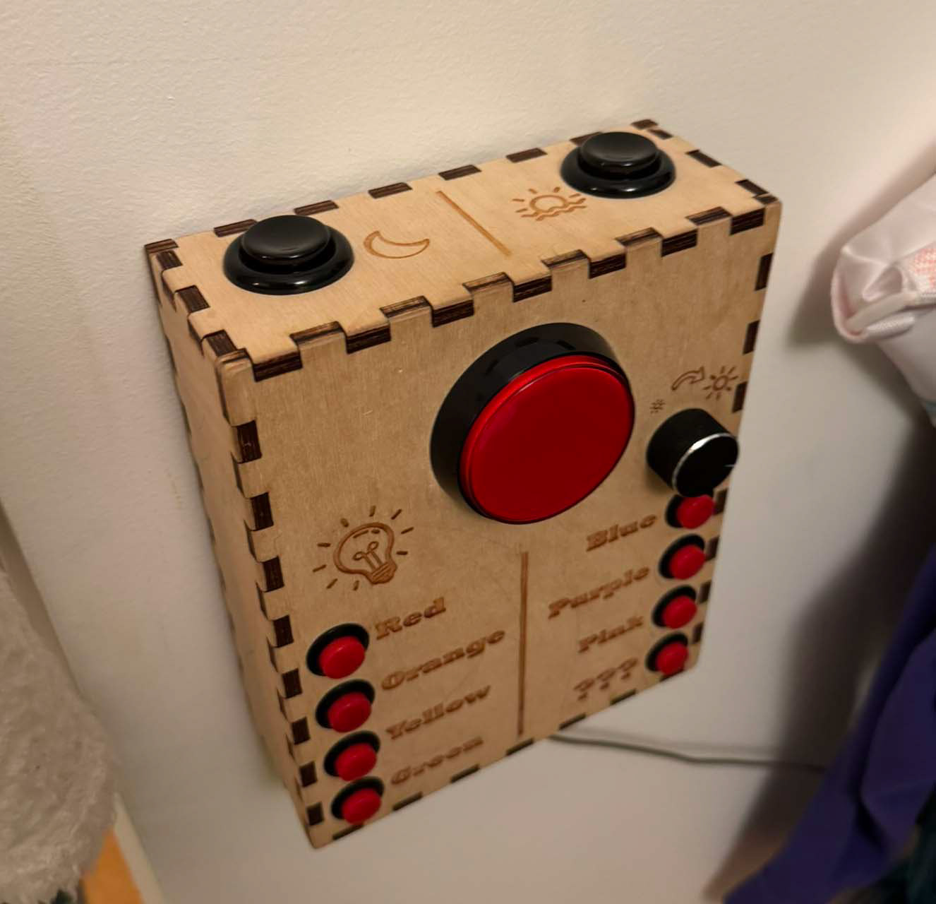
1) Offer a simple interface that could be wall-mounted at kid height
2) Include dedicated buttons for night time, wake up, and a brightness adjuster knob
3) Be indestructible... ish
For the brightness knob, I selected a rotary encoder, since the brightness level of the room could be modified by other controllers, the knob would not be able to be correctly aligned with the current scene. This meant that a potentiometer was out, and a rotary encoder was the better choice. Choosing a 20 step encoder, the action of rotation and the direction of rotation can be determined by an A/B channel quadrature measurement.
The interesting challenge here was that the ESP-8266 module I was using had only 9 GPIO, but I wanted to run 11 buttons and a knob. The Solution here was to use a matrix encoding scheme to poll the buttons, somewhat similar to how many keyboards work. By having 3 activation channels, and 4 receiving channels, I could use 7 pins to poll 12 buttons. This left one switch for the primary on-off button, and one output to drive a status LED for the big red button. Getting these buttons to work effectively during a matrix sweep was actually a bit challenging. There was some significant debounce filtering necessary to make sure pressing a button didn't trigger multiple activations when transitioning between different activation channels. Using a relatively low 30Hz polling rate also helped, since the system didn't need the speed of response necessary for a traditional keyboard. The main driver for minimum polling rate ended up being how fast the brightness knob could be turned, since those two channels were also part of the matrix encoding! I had to do some tests spinning as fast as I could to see if I could get incorrect direction registrations or skipped counts.
The reason for the dedicated line for the large central button, is that I wanted a way to update the firmware via a USB port without requiring the device to be disassembled. GPIO #0 serves as a a trigger to enter the bootloader when held low during power-on. By holding the large button while plugging in the USB port (which delivers power) it allows me to upload new code to the system without disassembly.
As of time of writing, this light switch has been used every day for 7 years, and other than some creative artistic additions by aspiring toddlers, looks just like it did on day one!